On this page
- Get your two numbers before you open any chart
- The chart, by horsepower and voltage
- Why a 115V chart and a 230V chart for "the same" motor look nothing alike
- Upgrading a well with wire already in the ground? There's a formula for that
- Aluminum wire: the exact substitution, not "go bigger"
- Grounding, if there's no metal conduit back to the panel
- Where the control box has to sit in that run
- A wire sized right at the chart's limit isn't automatically fine
- When this needs a pro
- FAQ
Last Updated on October 14, 2026 by umar bwn
A 230V, 1 hp submersible well pump needs 14 AWG copper for a total run up to 250 feet, 12 AWG to 400 feet, or 10 AWG to 630 feet — Franklin Electric’s voltage-drop chart, not a generic AWG calculator. And “total run” is the detail nearly every chart gets wrong: it’s two distances added together, not one guess.
The horizontal piece is the trench from the breaker panel out to the wellhead — the distance every generic calculator asks for and stops there. The vertical piece is the drop from the wellhead down to the motor, and on most residential wells that’s the larger of the two. It’s also the one you’re least likely to already know, because it isn’t something you can pace off at the surface.
Get your two numbers before you open any chart
One-minute check: pull your well log or driller’s report for the static water level and the pump’s setting depth — that’s your vertical number. Then check the as-built drawing, the permit survey, or just measure the trench route from the panel to the wellhead — that’s your horizontal number. Add them together. That sum, not either number alone, is what every table below is built around.
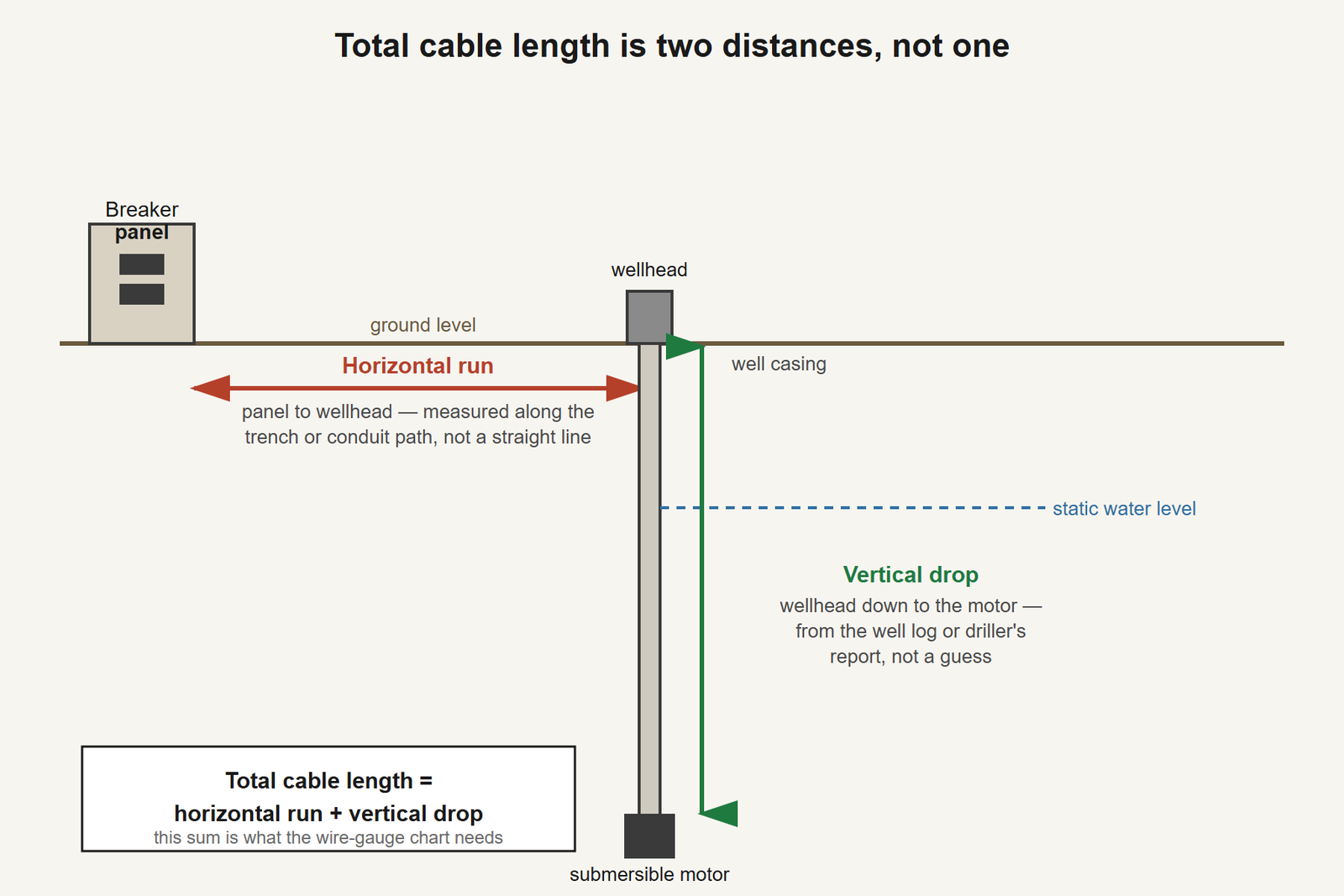
Skip this step and it’s easy to size wire for 150 feet of trench and ignore the 180 feet of well below it — which is exactly the mistake that produces a motor that hums, starts sluggishly on a hot afternoon, or trips intermittently for a reason nobody can find, because the wire was never sized for the run it’s actually in.
The chart, by horsepower and voltage
This is Franklin Electric’s own cable-selection table — 4-inch, single-phase, 75°C motors, copper wire, built around a 5% voltage drop at full nameplate amperage. “Total cable length refers to the cable between the power supply and the motor,” per the manual, which is the number from the step above.
| Volts | HP | 14 AWG | 12 AWG | 10 AWG | 8 AWG | 6 AWG |
|---|---|---|---|---|---|---|
| 115 | 1/2 | 100 ft | 160 ft | 250 ft | 390 ft | 620 ft |
| 230 | 1/2 | 400 ft | 650 ft | 1,020 ft | 1,610 ft | 2,510 ft |
| 230 | 3/4 | 300 ft | 480 ft | 760 ft | 1,200 ft | 1,870 ft |
| 230 | 1 | 250 ft | 400 ft | 630 ft | 990 ft | 1,540 ft |
| 230 | 1.5 | 190 ft | 310 ft | 480 ft | 770 ft | 1,200 ft |
| 230 | 2 | 150 ft | 250 ft | 390 ft | 620 ft | 970 ft |
| 230 | 3 | 120 ft | 190 ft | 300 ft | 470 ft | 750 ft |
| 230 | 5 | — | 110 ft | 180 ft | 280 ft | 450 ft |
Two things worth knowing before you read this as gospel. First, these figures are for copper. Aluminum needs its own rule, below — it isn’t “round up a size.” Second, 5% is the standard allowance, not the only one. The manual gives a second figure almost nobody reproduces: multiply the 5% length by 0.6 to get the maximum length for a 3% voltage drop. If your supply is already marginal — a long utility feeder, a rural co-op line, a generator — 3% is the more conservative number to design to, and it’s a straight multiplication, not a different table.
A retailer FAQ that ranks for this query caps its own version of this chart at 100 feet and says only “longer distances require thicker gauge wire,” with no numbers past that line. For most residential wells, 100 feet doesn’t even cover the vertical drop alone.
Why a 115V chart and a 230V chart for “the same” motor look nothing alike
Look at the ½ hp row above. On 14 AWG, 115V is good for 100 feet. 230V is good for 400 feet. Same motor, same wire, four times the allowed length.
That’s not a rounding difference and it’s not a typo — it’s the actual physics, and the reason matters because it tells you which number on the nameplate to trust. Halving the voltage for the same power roughly doubles the current the motor draws. Voltage-drop percentage scales with current multiplied by length, so if current doubles, the length you can run before you hit the same 5% drop falls by a factor of four, not two. Every generic AWG calculator just takes volts as a text box and never explains why the number swings so hard — which is also why pulling a 115V chart by mistake for a 230V motor (or the reverse) doesn’t give you a “close enough” answer. It gives you a wire that’s either wildly over-spec’d or dangerously short.
One-minute check: read the nameplate voltage off the motor before you touch any chart. The horsepower sticker on an old control box lid is not reliable for this — Franklin’s own documentation is blunt that control boxes and motors have to be verified by exact model code, not by the number stamped on the lid, and the same caution applies to confirming voltage before you size wire.
Upgrading a well with wire already in the ground? There’s a formula for that
This is the situation almost nobody writes about, and it’s the one that actually comes up on a pump replacement rather than a fresh well: some of the run is old wire already buried, and you’re adding new wire at a different gauge to finish the job. Looking up “310 feet, what gauge” in isolation gives you the wrong answer, because the old segment has already spent part of your voltage-drop allowance before the new segment even starts.
Franklin’s manual gives its own worked example, and it’s worth following through because the “obviously adequate” answer turns out to be wrong:
A replacement well already has 160 feet of buried #10 AWG copper between the service entrance and the wellhead. A new 3 hp, 230V motor goes in, and the remaining run to the motor is 310 feet. Looked at alone, 310 feet looks like a job for #8 AWG — the chart above shows #8 good for 470 feet at 3 hp. But the existing 160 feet of #10 has already used part of the allowance:
- A 3 hp motor can run 300 feet on #10 AWG. The existing wire is 160 feet, so 160 ÷ 300 = 53.3% of the allowable voltage drop is already spent before the new wire starts.
- That leaves 46.7% for the new 310-foot segment.
- Check #8 AWG: 310 ÷ 470 = 66.0%. Add the two: 53.3 + 66.0 = 119.3% — over the limit. Fails.
- Check #6 AWG: 310 ÷ 750 = 41.3%. Add the two: 53.3 + 41.3 = 94.6% — under the limit. Passes.
The manual’s own conclusion: #6 AWG is required for the new 310-foot segment, not #8 — even though #8 alone would look adequate for 310 feet taken by itself. The rule, in plain terms: add up what percentage of each wire’s own maximum length you’re actually using, across every gauge in the run, and the total has to stay under 100%.
A real case from this same situation, discussed on Terry Love’s plumbing forum: a homeowner with a 2 hp, 230V submersible (9.5A draw, 20A breaker) had a 420-foot total run split as 200 feet from the breaker to shore and 220 feet from shore to the pump. The pump manufacturer’s chart said 10 AWG was good to 411 feet — nine feet of margin on a 420-foot run, right at the printed edge of the table rather than comfortably inside it. Experienced posters on the thread didn’t tell him to just run 10 AWG and accept the nine feet. They recommended splitting the run into two gauges — roughly #8 AWG for the first 210 feet, #10 AWG for the remaining 220 feet — which puts him inside the chart with real margin instead of skating its limit. That’s the same combination-of-gauges principle the manual formalizes with its percentage rule, arrived at independently by forum consensus.
One-minute check: before you mix gauges, write down the length and gauge of what’s already in the ground and the length and gauge you’re adding. You need both numbers to run the percentage check — the new segment’s length alone isn’t enough information, no matter how adequate it looks on its own.
Aluminum wire: the exact substitution, not “go bigger”
Several pages mention aluminum wire for a well pump run in passing — “use a larger gauge” — without saying how much larger. The manual’s rule is exact: aluminum conductors must be two AWG sizes larger than the copper figure the chart calls for, and an oxidation inhibitor is required at every connection. The manual’s own example: if the chart calls for #12 copper, the aluminum equivalent is #10, not #11 and not “whatever’s on the shelf a bit bigger.” Skip the oxidation inhibitor and the aluminum-to-copper (or aluminum-to-brass) connections at the panel and the motor leads are exactly where that substitution fails first.
Grounding, if there’s no metal conduit back to the panel
This one matters most on an older well being rewired rather than a fresh install, where the original ground path may have been the metal well casing or a run of metal conduit that’s since been replaced with PVC. The manual’s rule: if the circuit has no grounding conductor and no metal conduit from the supply panel to the motor, run a dedicated ground wire at least as large as the line conductors, connected from the motor’s grounding terminal back to the electrical supply ground per NEC.
There’s a specific exception worth knowing if the well water is genuinely corrosive and the drop pipe and casing are plastic rather than metal: the manual specifies a GFCI with a 10 mA set point, with the ground wire itself routed through the same current-sensing device as the power leads — so the GFCI only trips if the ground wire stops doing its job, not on ordinary leakage. That’s a narrower, more specific device than a standard GFCI breaker, and it’s worth asking for by that spec rather than “a GFCI” generically.
This site’s article on well pump surge arrestors covers a different ground entirely — the arrestor’s own earthing, which the manual requires below the lowest drawdown water level. That’s about protecting the motor from a lightning-induced surge. This section is about the line conductors’ own ground path. A well can need both and they’re not the same wire.
Where the control box has to sit in that run
If the motor is a 3-wire type with a control box that includes a line contactor, there’s a placement rule that has nothing to do with wire gauge and everything to do with where the box physically sits: the cable length between the power supply and the control box should not exceed 25% of the total allowable maximum cable length, or the contactor can stop operating reliably. A control box without a line contactor doesn’t have this restriction — it can sit anywhere in the run.
This is the detail that bites on a long horizontal run from a detached pump house or an outbuilding, where it’s tempting to mount the control box close to the well rather than close to the power source. If your existing box is the wrong type for that placement — or if you’re not sure whether it has a line contactor at all — this site’s buying guide to well pump control boxes covers exactly that distinction, including why a CRC box and a plain QD box can carry the identical horsepower rating and still not be interchangeable.
One-minute check: measure (or estimate from the panel-to-wellhead-to-box routing) how far the control box sits from the power supply as a fraction of your total cable length. Past roughly a quarter, a line-contactor box is working outside its documented placement.
A wire sized right at the chart’s limit isn’t automatically fine
This site’s article on well pump breaker trips makes the point that the breaker “is not protecting the pump — it’s protecting the wire in the wall, which is sized for a specific current and does not get bigger because the breaker did.” The wire-gauge chart above is the other half of that sentence: it’s what decides whether the wire in the wall was ever adequate in the first place.
Here’s the mechanical link nothing on the open web draws, and it connects directly to a symptom this site has already verified. Franklin’s own voltage tolerance for these motors is ±10% of rated voltage, which in plain figures is 207–253V for a 230V motor — published on this site’s article on a well pump clicking but not starting. A wire run sized to exactly the 5% voltage-drop limit is, by definition, allowing the motor to see up to 5% less voltage than the panel supplies. Combine that with a utility supply that’s already sagging toward the low end of its own tolerance — a hot afternoon, every air conditioner on the street running, a long utility feeder — and the two add up. A wire that “passes” the chart at its exact maximum length and a supply that’s merely adequate, not generous, can together land the motor below 207V. That’s not a hypothetical: it’s the direct, physical path from “wire sized at the limit” to “pump hums and doesn’t start,” one cause feeding the other.
One-minute check: measure voltage at the pressure switch while the pump is actually trying to start, not while it’s idle — the same trap as taking a pressure reading with the whole house shut off. If the reading is low and your wire run is at or near the chart’s printed maximum, the wire is a legitimate suspect sitting right alongside the utility supply, not a separate problem to rule out later.
When this needs a pro
Everything past reading a well log and a nameplate. This is a 230V (sometimes 115V) circuit, usually run through wet ground or a damp pump house, and the work that follows from this chart — pulling new conductors, splicing two gauges together correctly, running a dedicated ground conductor, or deciding whether a corrosive-water GFCI applies to your well — is exactly the kind of work the National Electrical Code governs and a licensed electrician is trained and insured to do. Sizing the wire from a chart is something you can do yourself with a tape measure and a well log. Opening the panel, the wellhead junction box, or the control box to actually run or terminate that wire is not a DIY step on this one.
FAQ
I’m close to the chart’s maximum length. Is that actually fine, or do I need margin?
Treat the printed maximum as the point where the formula fails, not a safe target to aim for. The real-world example above — a run nine feet under a 411-foot limit — was treated by experienced installers as “right on the edge,” not comfortably inside it, and their fix was to split the run into two gauges for real margin rather than accept the nine feet. A supply voltage that’s already a little low, or a hot day with heavy demand elsewhere in the house, eats into that margin from the other direction.
If my wire is right at the chart’s limit, will the pump still start on a hot afternoon?
Possibly not reliably. A wire sized to the chart’s 5% drop limit assumes the panel is delivering full rated voltage. On a hot afternoon, with air conditioning and other loads pulling the street’s supply voltage down toward the low end of its tolerance, the combination of supply sag and a wire already using its full allowance can put the motor below its 207V floor on a 230V circuit — which reads as exactly the clicking-and-humming, won’t-start symptom covered elsewhere on this site.
Can I use a 2-pole GFCI breaker on a 2-wire well pump circuit?
Installers discussing this on Terry Love’s forum confirmed a 2-pole GFCI breaker works fine on a standard 2-wire submersible circuit. Whether your situation needs GFCI protection at all, and which type, is a code and site-condition question for a licensed electrician — this just answers the compatibility question, not the requirement question.
Does the NEC ampacity table give the same wire length as the pump manufacturer’s chart?
No, and this is worth knowing before you compare two sources and get two different answers. NEC ampacity tables size a conductor for heat — how much current it can carry without overheating, for a given length and installation method. The manufacturer’s chart above sizes for voltage drop at the motor, which is a tighter constraint in most well-pump situations because a long run can run cool while still dropping more voltage than the motor tolerates. Well pump installers generally work from the manufacturer’s voltage-drop chart for exactly that reason — it’s the one built around the thing that actually makes these motors fail to start.