On this page
Last Updated on October 7, 2026 by Muhammad Toqeer
Your pump is hanging a couple of hundred feet down on threaded pipe. Every page about this says the joints should be tight. One of them says how tight:
“The minimum torque should never be less than 10 foot-pounds times the motor nameplate hp rating.”
A torque specification scaled to the motor. One horsepower gives ten foot-pounds as the floor. A one-and-a-half horsepower motor gives fifteen.
And the reason it scales is the thing worth understanding — because what tries to undo those joints is not the weight of the pipe. It is the motor, twisting, every single time it starts.
The four verification items
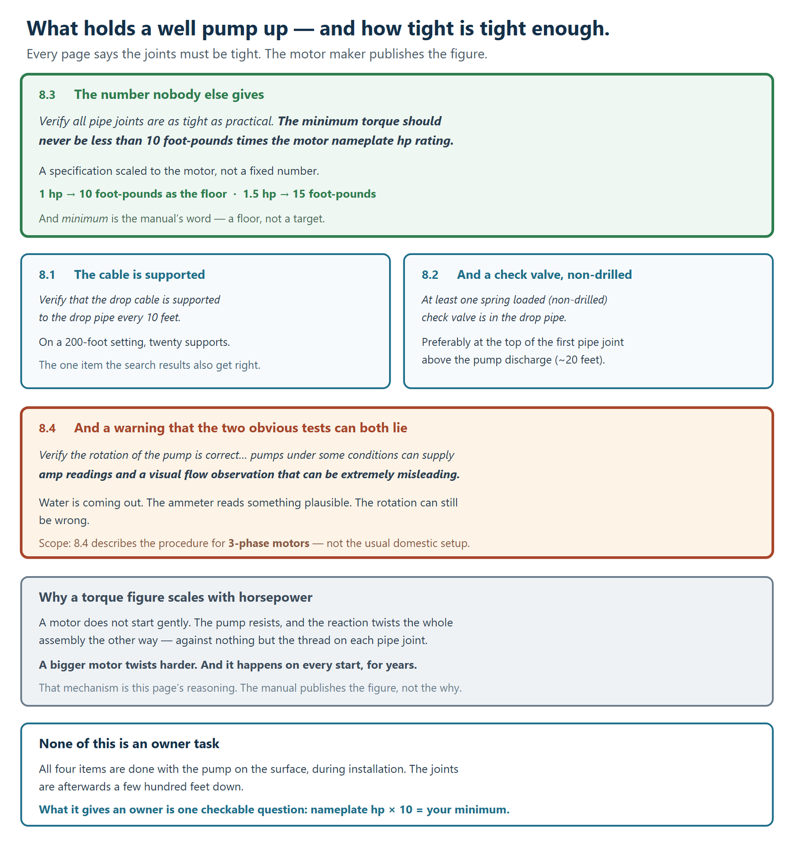
From Franklin Electric’s AIM Manual, section 8.0, Motor-Pump Installation. All four items verbatim:
8.1 “Verify that the drop cable is supported to the drop pipe every 10 feet.”
8.2 “Verify at least one spring loaded (non-drilled) check valve is in the drop pipe. Preferably, the first check valve should be located at the top of the first pipe joint above the pump discharge (~20 feet) if the pump does not have a check built in to its discharge.”
8.3 “Verify all pipe joints are as tight as practical. The minimum torque should never be less than 10 foot-pounds times the motor nameplate hp rating.“
8.4 “Verify the rotation of the pump is correct… pumps under some conditions can supply amp readings and a visual flow observation that can be extremely misleading.“
Four items, and they are one subject: the pump stays where it was put, connected to what it was connected to.
Why a torque figure scales with horsepower
This part is the page’s own reasoning rather than the manual’s, and it is worth stating because it makes the number make sense.
A motor does not start gently. It goes from nothing to full rotation, and the pump it is turning resists. That reaction twists the whole assembly in the opposite direction — and the only thing holding the assembly against that twist is the thread on each pipe joint.
A bigger motor twists harder. So the minimum tightness has to rise with it, which is exactly what “10 foot-pounds times the motor nameplate hp rating” does.
And it happens on every start, for years. Not once at installation — thousands of times.
Which is why the specification is a minimum rather than a target. The sentence it sits in is “Verify all pipe joints are as tight as practical”, and the formula is the floor below which “as tight as practical” has not been achieved.
The cable is supported, not hung
8.1 “Verify that the drop cable is supported to the drop pipe every 10 feet.”
Every ten feet, all the way down. On a two-hundred-foot setting that is twenty separate supports.
The cable is not meant to carry anything. It is secured to the pipe so that it hangs with the pipe rather than from its own connections — and so that it is not loose in the casing where it can be rubbed, snagged or fouled.
This is the one item the rest of the internet does get right, and several installation pages carry the ten-foot figure. It is confirmation rather than a discovery, and it is in the manufacturer’s own list.
The check valve item, and where it is already covered
8.2 “Verify at least one spring loaded (non-drilled) check valve is in the drop pipe.”
Note “non-drilled” — a check valve with a hole deliberately put in it is specifically excluded, and the position given is “the top of the first pipe joint above the pump discharge (~20 feet)”.
The consequence of getting this wrong is set out in full elsewhere on this site — Franklin’s warning about a pump starting under zero head, the upthrust that puts on the impeller and the motor, and what repeated upthrust does to both. That article owns the mechanism, and this one does not repeat it.
What belongs here is only that it is on the hanging checklist at all, which tells you the check valve is part of how the installation is put together rather than an accessory bolted on afterwards.
The rotation check, and a warning worth keeping
Item 8.4 contains the most quietly alarming sentence in the section:
“…pumps under some conditions can supply amp readings and a visual flow observation that can be extremely misleading.”
Read what that is saying. Water is coming out. The ammeter reads something plausible. And the rotation can still be wrong.
The two tests anyone would naturally reach for are both capable of lying, which is why the manual calls checking flow and current in both directions “best practice” rather than optional.
One scope note, stated rather than quietly dropped: item 8.4 describes the procedure for 3-phase motors, and names swapping two leads as the method. That is not the usual domestic configuration. The warning about misleading observations is worth knowing whatever you have; the procedure is for a machine most houses do not own.
What this means if you are the owner rather than the installer
You are not going to check any of this. All four items are performed with the pump out of the well, on the ground, by whoever is putting it in.
What it gives you is a vocabulary.
Ask whether the joints were torqued to the motor’s rating rather than hand-tight. That one question tells a contractor you have read something.
Ask what the pump is set at and how the cable was secured. Setting depth has constraints of its own that are nothing to do with hydraulics, and the two conversations belong together.
And keep the paperwork. So much of what matters about a submersible is unverifiable once it is down the hole that the installation record is the only evidence that survives.
And if a pump has failed early with no obvious cause, the questions on this page are reasonable ones to ask before buying the same thing again.
When this needs a pro
All of it, without qualification.
Every item in section 8.0 is performed during installation, with the pump on the surface and the well open.
Pulling or setting a submersible. Hundreds of feet of pipe, cable and water, and the heaviest job on a domestic well.
Anything involving rotation or leads. Item 8.4’s own method is to have “the electrician” swap two leads — the manual assumes an electrician is present.
And re-torquing anything. The joints are down the well. There is no owner-accessible version of this task.
What you can do yourself: find the motor’s nameplate horsepower on your paperwork and multiply it by ten. That is the published minimum torque figure for your installation, in foot-pounds — and it is a specific, checkable thing to ask about rather than a vague worry.
FAQ
How tight should well pump drop pipe joints be?
The motor manufacturer publishes a minimum: never less than 10 foot-pounds times the motor nameplate horsepower rating. It sits alongside the instruction that all pipe joints should be as tight as practical, so the formula is a floor rather than a target.
Why does the torque requirement depend on horsepower?
Because the motor’s starting torque is what tries to undo the joints, and a bigger motor twists harder. That reasoning is this page’s rather than the manual’s — what the manual publishes is the scaled figure itself.
How often is the drop cable supposed to be secured?
Every 10 feet, to the drop pipe. On a 200-foot setting that is twenty supports, and the purpose is that the cable hangs with the pipe rather than from its own connections.
What is a non-drilled check valve?
A check valve without a hole deliberately put in it. The checklist asks for at least one spring-loaded, non-drilled check valve in the drop pipe, preferably at the top of the first pipe joint above the pump discharge — about 20 feet — where the pump has no check built into its discharge.
Can you tell pump rotation by whether water comes out?
The manufacturer says not reliably. Its checklist states that pumps under some conditions can supply amp readings and a visual flow observation that can be extremely misleading, which is why it asks for flow and current to be checked in both directions.
Is any of this something a homeowner can check?
No. All four items are carried out with the pump out of the well during installation. What an owner can do is read the nameplate horsepower, multiply by ten, and ask whether the joints were torqued to that figure.