On this page
- Is this your job?
- 1. Look before you test anything
- 2. Discharge the capacitor — this is the step the "it's a pro job" advice is really about
- 3. Test the capacitor — and read the result correctly
- 4. Figure out which box you have, then test the relay
- 5. Test the overload
- 6. Test the motor windings — at the control box, not at the well
- 7. Test insulation resistance
- 8. What it means when everything passes and the pump still won't run
- When this needs a pro
- FAQ
Last Updated on October 12, 2026 by umar bwn
Every ranking page gives you the same instruction for the capacitor: set the meter to ohms, watch the needle swing toward zero, then back toward infinity. That rule is wrong for roughly a third of the capacitors you’ll meet. Franklin Electric’s own service manual tests the capacitor, the relay, the overload and the windings separately, with the power off, and gives an actual pass/fail number for each — numbers the generic version never mentions.
Is this your job?
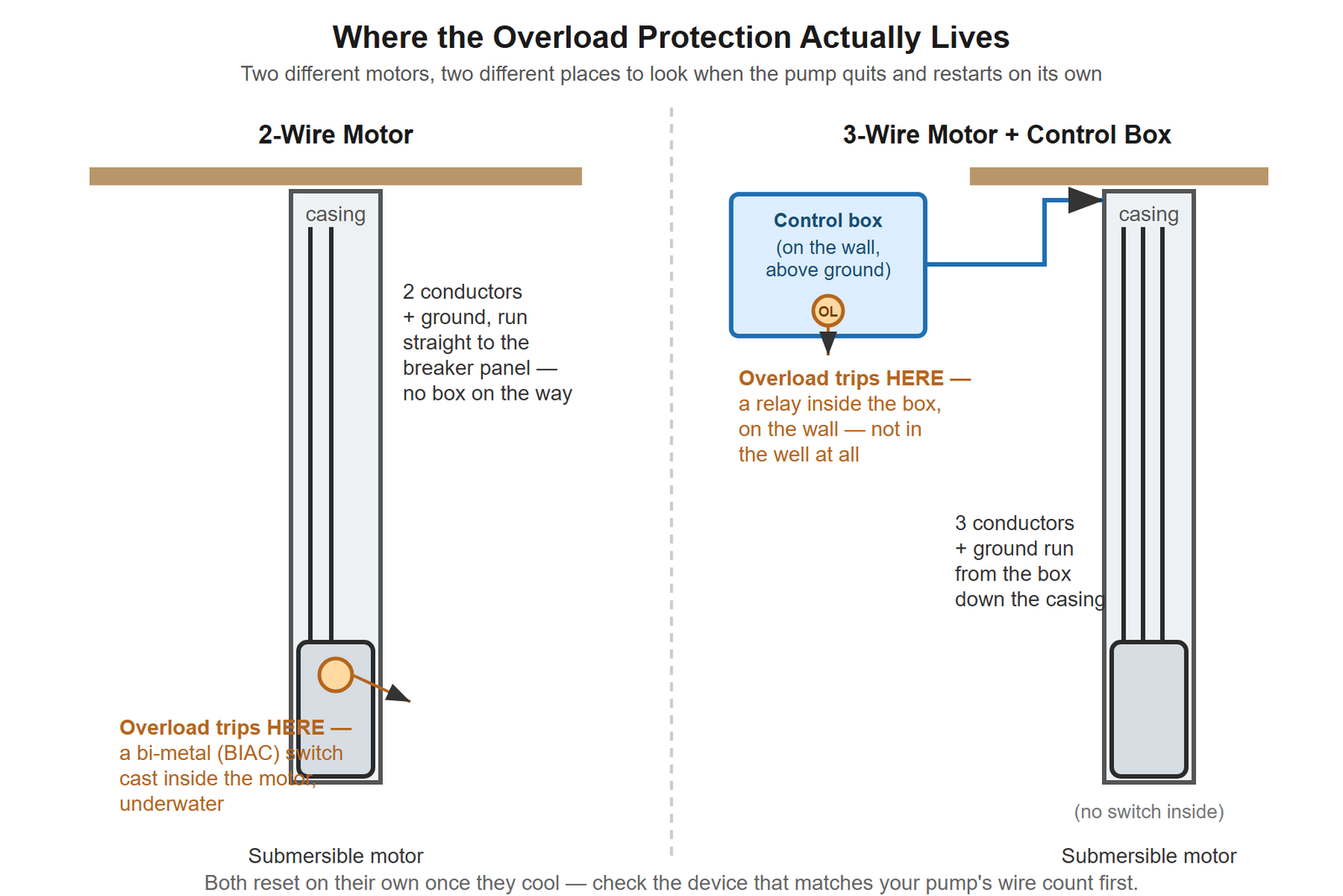
Two kinds of control setups have something worth ohmmeter-testing: a 3-wire submersible system, where the relay, capacitor and overload sit in a box on the wall, and a jet pump, where the start/run capacitor sits in a box mounted on the motor itself. If you counted the wires going down your well and found only two, stop here — a 2-wire motor has no capacitor and no control box to open. Franklin builds those motors “control-box less,” with the starting switch sealed inside the motor itself, underwater. What a clicking 2-wire pump is actually doing is a different article, not a shorter version of this one.
What you need
- A multimeter or ohmmeter that reads resistance down to single ohms and up through at least R×100k (most basic digital multimeters do all of this on autorange; an analog meter needs the R×1 / R×100 / R×1,000 / R×100k switch positions called out below)
- An insulated screwdriver, or a 20,000-ohm 2-watt resistor and insulated pliers, for discharging the capacitor
- A flashlight and a way to note which wire came off which terminal before you start disconnecting anything
- Your motor’s own nameplate or spec sheet, if you still have it — the winding-resistance step is meaningless without it
Before you touch anything
This is a 240-volt circuit and a capacitor that can hold a charge after the breaker is off. Shut the breaker off at the panel and confirm it’s dead with a non-contact tester or a meter across the line terminals before the cover comes off. Everything below is done with the power off. Where the manual’s own tests require power back on, that’s called out explicitly, and that’s also where this stops being a one-person-with-a-multimeter job.
1. Look before you test anything
Open the box. A swollen or split capacitor case, a scorched relay, or a connection that’s gone green and loose tells you more in ten seconds than the first three ohmmeter readings will. Note it, but test anyway — a capacitor can look fine and still be dead, and a connection that looks fine can still be the fault once you wiggle it with the power off.
2. Discharge the capacitor — this is the step the “it’s a pro job” advice is really about
A companion article on this site treats capacitor testing as trade territory, and the reason is real: a capacitor stores a charge after the breaker is off, sometimes for a long time, and touching both terminals at once is how people get a surprise shock off a “dead” circuit. That risk doesn’t go away by being careful about wires — it goes away by discharging the thing on purpose, first, every time.
Lay an insulated screwdriver blade across both capacitor terminals for a couple of seconds, or hold a 20,000-ohm resistor across them with insulated pliers. You may see a small spark or hear a faint crack. Once that’s done, you’re testing a drained component with a meter, the same as any other dead circuit — which is exactly what the next step is.
3. Test the capacitor — and read the result correctly
Set the meter to R×1,000 and touch a lead to each capacitor terminal.
A good capacitor: the needle swings sharply toward zero, then drifts back out toward infinity as the meter’s own small current recharges it.
Here’s the part every ranking page skips: some capacitors are built with a bleed resistor across them — a safety feature, not a fault — and Franklin’s own table says those will drift back to 15,000 ohms, not true infinity. Tested against the generic “back to infinity or it’s bad” rule, a perfectly good capacitor with a bleed resistor fails. It shouldn’t.
A bad capacitor reads one of two ways instead: stuck at or near zero (shorted), or no swing at all, sitting at infinity from the first touch (open).
One honest caveat, straight from the manual: “a capacitor may test good (not open, not shorted) but may have lost some of its capacitance and no longer be able to perform its function.” An ohmmeter catches the capacitor that’s dead. It doesn’t catch the one that’s just tired.
4. Figure out which box you have, then test the relay
Control boxes split into two families, and the relay test is different for each. Look for a model tag — “QD” or “Quick Disconnect” on one side, a solid-state relay module on the other; “Integral Horsepower” or a mechanical potential relay (it looks like a small black cube with a visible coil) on the other.
QD (solid-state) box:
- Relay coil, meter on R×1 — should read zero ohms across the board, all models.
- Relay triac, meter on R×1,000, across the cap-to-B terminal — should read infinity, all models. Any resistance here means the triac is shorted.
Integral Horsepower (potential relay) box:
- Relay coil, meter on R×1,000, across the L1 and B terminals — 0.7–1.8 ohms on the R×1,000 scale (700–1,800 ohms actual) for 115-volt boxes; 4.5–7.0 ohms (4,500–7,000 ohms actual) for 230-volt boxes. Mixing these up is easy if you don’t know your box’s voltage first.
- Relay contacts, terminals #2 and #5, meter on R×1 — should read zero ohms.
- Contacts #1 and #2, manually closed, meter on R×1 — should also read zero ohms.
5. Test the overload
With the overload’s contacts pushed closed, meter on R×1 — a good overload reads less than 0.5 ohms. Anything meaningfully higher means the contacts themselves have degraded, independent of whether they’re tripping correctly.
If the overload keeps tripping after you’ve reset it once, this test tells you whether the overload itself is the problem or just the messenger for a fault somewhere else — a bound pump or a short will trip a perfectly good overload just as fast.
6. Test the motor windings — at the control box, not at the well
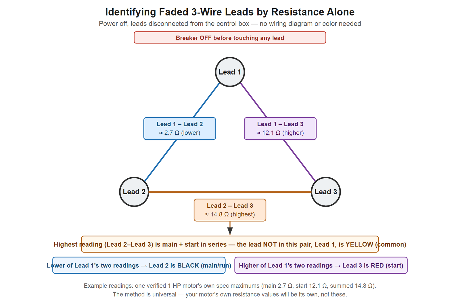
Disconnect the motor leads from the box. On a 3-wire motor you’re measuring two pairs: yellow-to-black (the main or run winding) and yellow-to-red (the start winding). Use R×1 for anything under 10 ohms, and step up to the next scale above that.
There is no single number here — Franklin states plainly that winding resistance varies by horsepower and model, so the only number that matters is the one on your motor’s own spec tag. A real example from a forum thread on a dead secondary well pump: that motor’s 1 HP spec sheet listed a 2.7-ohm maximum on the main winding and 12.1 ohms on the start winding. Multiple meters on that same motor read 3.2–5.5 ohms and 11.8–13.7 ohms respectively — both over spec on both windings, which is how the actual fault was found after the capacitor and the box’s own self-test both came back clean.
That case is worth sitting with for a second, because it’s the one every generic guide misses entirely: a capacitor that “reads perfect” and a control box that passes its own self-test are not proof the pump is fine. A box can pass its internal check and still, as one forum tradesperson put it, “just not be closing the circuit.” The winding numbers were the only reading that actually pointed anywhere.
If the leads are faded or unmarked
You can still sort yellow from black from red with nothing but the ohmmeter. Measure resistance between all three pairs of leads — call them 1-2, 2-3, and 3-1. Whichever lead is not part of the highest-resistance pair is yellow (common), because that pair is reading the main and start windings in series. Of yellow’s two remaining readings, the higher one is red (start) and the lower one is black (main/run).
7. Test insulation resistance
This one catches a different kind of failure — moisture inside the motor or a nicked cable, not a burnt winding. Use a megohmmeter at 500 VDC if you have one, or an ohmmeter set to R×100k. Leads disconnected from the box, breaker off, same as every step above.
| Condition | Reading |
|---|---|
| Used motor, about to go back in the well | 200.0 megohms or more |
| New motor with drop cable, not yet installed | 10.0 megohms or more |
| Motor already in good condition, in the well | 2.0 megohms or more |
| Insulation damage — locate and repair | 0.50–2.0 megohms |
| Failed | Below 0.50 megohm |
That first row looks backward until you think about why it’s there: a motor you’re about to lower back down a well needs more margin than one that’s already running fine down there, because the next chance to check it is whenever it fails again. The middle band — 0.5 to 2.0 megohms — is the one every quick online guide erases into a single pass/fail cutoff. It isn’t pass or fail. It’s “there’s damage, and it’s still findable.”
8. What it means when everything passes and the pump still won’t run
This happens, and it’s exactly the situation from the forum case above: capacitor clean, box self-test green, and the motor still draws no current. At that point the manufacturer’s own tests have run out of things to check that don’t require power, and the next move isn’t to assume the motor is dead — it’s to swap the control box itself before pulling anything out of the ground, since a box can fail in a way its own self-test doesn’t catch. If you’re at that point, our guide to well pump control boxes covers what actually separates one box from another by amperage rating and body size, not just the badge on the front.
When this needs a pro
Anything measured with the cover off and the power back on. The manual’s own voltage and current tests are explicit that “power must be on for these tests” and warn against touching live parts — reading line voltage within 10% of nameplate, or watching the red (start) lead’s current spike and drop within about a second to confirm the relay actually switched out, is routine for an electrician and genuinely dangerous done casually on a live 240-volt box.
Anything that means pulling the pump. If the windings or insulation reading comes back failed, that’s a motor decision, not a control-box one, and it’s a two-person job with the right equipment.
A breaker that won’t stay reset, or one that trips the instant you restore power with the box disconnected. That’s a different diagnostic path than anything above, because the fault isn’t inside the box at all.
Replacing any part that fails. Testing tells you what’s wrong. Swapping a capacitor, a relay or a board inside a box that’s still energized at the panel is where this becomes a trade job again.
FAQ
Do I need a megohmmeter, or will a regular multimeter work?
A regular multimeter works for every ohms test in this guide, including insulation resistance, as long as it has an R×100k range (or reads resistance into the hundreds of thousands of ohms on autorange). A dedicated megohmmeter tests at 500 volts DC and is more sensitive to borderline insulation damage, but it isn’t required to get a usable pass/fail reading.
My control box’s self-test LEDs are all green, but the pump still won’t run. What does that mean?
Less than it looks like. A box’s internal self-test checks that its own components are responding, not that the circuit between the box and the motor is actually closing. A clean self-test plus a clean capacitor reading is not proof the fault is somewhere else — check the winding resistance against the motor’s own spec numbers before assuming the pump itself has failed.
Does this apply to a jet pump’s capacitor the same way?
The capacitor test itself — discharge first, R×1,000, swing toward zero and back — is the same component and the same procedure whether it sits in a submersible control box on the wall or in a box mounted on a jet pump’s motor. The relay, overload and winding-at-the-box steps are specific to 3-wire submersible systems, because a jet pump’s motor and its starting components are in one place you can already see and reach.
Can I test the capacitor myself, or is that always a pro job?
You can test it yourself once it’s discharged — that’s a meter reading on a drained component, no different from testing any other dead part. What takes judgment and the right equipment is replacing it in a box that’s still energized at the panel, and anything involving a live voltage or amperage reading with the cover off.