On this page
Last Updated on October 3, 2026 by Muhammad Toqeer
This is a piggyback switch swap, and the whole job is positioning. The pump plugs into the back of the switch, the switch plugs into the wall, and nothing is wired. What decides whether it works in six months is where the float sits and what is near it — not which switch you bought.
Three numbers from the manufacturer’s own sheet do most of the work. A #10-16 × ½ inch tapping screw, because “longer screws can crack the cover.” Two inches above the bottom of the pump base, which is a floor on the off level. And two inches below the turn-on level, which is where the cable tie goes — a different measurement doing a different job.
Before any of it: unplug the pump. And if your installation is direct-wired at 230 volts rather than plugged in, this is not your job — the maker’s own warning explains why, further down.
What you need, and what the sheet specifies

Parts and tools:
- The replacement switch, matched to your pump — and matching it is a decision with a real trap in it, because several floats sold alongside the pump-duty ones are 5-amp control switches meant for a panel
- The cord clamp and screw that came with it. If the screw is missing, the sheet names the substitute: “use only a #10-16 x ½” long tapping screw. Longer screws can crack the cover.“
- The cable tie supplied, for a universal installation
- A screwdriver, a tape measure, and a bucket of water for the test
And the clearances to check before you buy, because they are about your pit rather than the switch:
| Published minimum | Figure |
|---|---|
| Tether length | 3½ in. |
| Sump diameter, sump duty | 14 in. |
| Sump diameter, effluent and sewage | 18 in. |
If your pit is under those diameters, a tethered float is the wrong shape for it and no amount of careful fitting changes that.
The safety part, which decides whether you continue
Unplug the pump before touching anything. On a piggyback arrangement that means unplugging the pair from the wall, not just separating them.
And three conditions from the sheet that have to be true of your installation:
“Switch must be used with pumps that are equipped with three-prong grounding plugs. Do not remove the third pin from the plug.“
“Separate branch circuit is recommended. Do not use extension cord.“
“Be sure electrical connections cannot be reached by rising water. Under no circumstances should outlet box or receptacle be located where it may become flooded or submerged by water.“
That middle one matters more than it looks, because the moment you unplug a pump to swap a switch is the moment the cord suddenly seems too short. This site has the voltage-drop case against extension cords on a sump pump already — and here a second manufacturer says the same thing in a switch sheet.
Stop here if your pump is direct-wired at 230 volts. The sheet’s own warning:
“WARNING: In a 230V direct wire installation, one side of the line going to the pump is always HOT. This condition exists whether the float switch is ON or OFF.”
A switch that does not isolate the pump cannot make anything safe to touch. That installation needs an electrician and a double-pole disconnect, and nothing below applies to it.
The steps, as the manufacturer gives them
1. Unplug the pump and the switch from the outlet, and lift the pit cover.
2. Note where the old float sat before you remove it. The existing on and off levels are information you are about to destroy, and they were probably right.
3. Attach the cord clamp to the pump. From the sheet: “Attach cord clamp to pump cover. The clamp and pump handle must be positioned to allow free operation of float. Be sure to locate and switch power cords away from switch float.”
4. Set the tether length, which is the setting rather than a detail. The minimum is 3½ inches, and the length is what sets how much water moves per cycle — longer tether, deeper draw, fewer starts.
5. Hand-tighten the clamp screw. The sheet says “After desired tether length is established, hand tighten clamp screw” — hand tight, with the specified screw, on a plastic cover.
6. If you are fitting it as a universal switch rather than clamped to the pump, the sheet gives a separate route: “Attach switch cord using the cable tie provided to any convenient rigid surface about 2″ below the desired turn-on level. Do not tighten cable tie until turn-on and turn-off levels are established.“ Then: “Tighten cable tie securely after turn-on and turn-off levels are established.”
7. Check the off level against the hard limit. This is the CAUTION in the sheet:
“To prevent damage to pump, do not set switch turn-off level below 2″ above bottom of pump base.“
8. Make sure the pump cannot move. “Be certain that pump is secured in position so float cannot become stuck between the pump and the basin which could prevent pump from coming on or going off.”
The three things that trap a new float
Worth pulling out of the steps, because every one of them passes a bench test and fails weeks later.
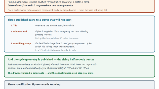
The pump moving in the basin. A pump that shifts when it starts can close the gap the float swings through. The sheet asks for it to be secured for exactly this reason.
The pump’s own handle. It is the thing most likely to be in the arc, and the instruction names it: the clamp and the handle have to be positioned to allow free operation.
The power cords. “Be sure to locate and switch power cords away from switch float.” Two or three cords in a pit — pump, switch, and an alarm or backup if you have one — and any of them can foul the float.
Pro note: all three are positioning rather than parts. A float that is stuck is the single most common thing behind a pump that will not start, and that diagnosis is its own page — which is worth reading now rather than in six months.
Testing it, in the order the sheet gives
Dry first, and briefly:
“Without water in sump, plug pump cord into the back of the switch plug. Plug switch into outlet. Lift float and listen for pump to operate. Do not run pump for more than 5 seconds.“
Five seconds, because the pump is running dry while you do it.
Then with water:
“Next, run water into sump where pump is installed. Fill the sump to the on level and allow the pump to remove water to the off level.”
Watch the whole cycle, not just the start. You are checking three things: that it starts where you wanted, that it stops where you wanted, and that the float swings the full travel without touching anything.
And watch the off level specifically against the two-inch rule. A pump that keeps running after the water is gone is a pump running dry on every cycle.
The routine test from here on is a separate schedule, and it is worth starting it the month after a switch change rather than a year later.
When this needs a pro
Any direct-wired installation, at 230 volts or otherwise. The manufacturer’s warning about one side of the line being permanently hot is the reason, and it is not a judgement call.
Anything inside the pump. A switch swap is external — a clamp, a cord and a plug. If the fault turns out to be inside the pump, that is a different job.
A pit below the published minimum diameter, where the honest answer is a different switch type rather than a careful fit.
And a pump that needed a new switch twice. That is the pit or the pump talking, not the switch, and replacing the smallest part a third time will not settle it.
An outlet that is not GFCI-protected, or that sits where water could reach it. The sheet is explicit about the receptacle, and correcting it is electrical work.
What you can do yourself, before deciding any of that: measure the pit’s inside diameter, count the cords already going through the lid, and check whether your outlet is above any plausible water line. Three things, one tape measure — and they tell you whether this is a ten-minute swap or a call.
FAQ
Can I replace a sump pump float switch myself?
On a piggyback switch, usually — the pump plugs into the back of the switch and the switch into the outlet, so nothing is wired. The job is positioning rather than electrical. A direct-wired installation is different: the maker warns that on 230 V one side of the line to the pump is always hot, on or off.
What screw do I use if the one in the box is missing?
The sheet names it: a #10-16 × ½ inch long tapping screw, and only that. It also says why — longer screws can crack the cover, which turns a switch swap into a new pit lid.
How low can I set the turn-off level?
Not below 2 inches above the bottom of the pump base. That is the manufacturer’s caution, and it exists to stop the pump running dry at the end of every cycle. It is a different measurement from the tie-point rule, which is about 2 inches below the desired turn-on level.
Why does a new float switch stop working after a few weeks?
Usually because something is fouling it rather than because it failed. The sheet names three: a pump that moves in the basin and traps the float against the wall, the pump’s own handle in the float’s arc, and power cords left near the float. All three pass a bench test.
How do I test the new switch?
Dry first — plug the pump into the back of the switch, plug the switch in, lift the float and listen, but do not run the pump more than five seconds because it is running dry. Then fill the pit to the on level and watch it pump down to the off level, checking the float swings freely the whole way.
Does the tether length matter?
It is the setting, not a detail. The published minimum is 3½ inches, and the length between the float and its tie point sets the on-off differential — longer means a deeper draw and fewer starts, shorter means shallower and more frequent ones.